Announcement

Collapse
No announcement yet.

MOD: Korg Monotribe Modification

Collapse
X
 
  • Filter
  • Time
  • Show
Clear All
new posts

  • MOD: Korg Monotribe Modification

    http://www.youtube.com/watch?v=3pfQJ70A15k

    I spent a day this week exploring the Korg monotribe..

    I'll detail all the mods when i get some time, but i did discover some of the info on the web so far re: modding the monotribe is WRONG,
    and this info has been copy/pasted all over the place.. SO, if you have had brain damage attempting to mod Yours, relax, i'll sort you out..
    Last edited by playthatbeat; Sun 10-01-2016, 8:38 PM.
    jUst plAythAtbEAt

  • #2
    So, let's write up what modifications i did to my Korg Monotribe.

    As usual, this information is offered for Your amusement, and i offer no guarantee any of it will work for You.

    sd noise decay - link to gnd (any of the board screws) thru' a non-polarised 103k cap or 100n film cap (250v).
    Some instructions on the web to increase the SD decay time are nonsense, claiming You need to use industrial resistors to get effect - use your head on this, a capacitor will deliver.
    Don't bother tinkering with the other SD points, unless you want to emphasize the BONG componant of the snare sound.. It's generated using transistor feedback, so if you mod it, expect strange (ie: crap) interactions and a pretty useless sound - stick to the noise portion decay.
    I used 2 different values for this on the blue switch far right of the 'matrix' pic below, one is stupid long so on the non-latching side of the switch, the other is a very nice snare length, so i made it latching.

    bd decay - gnd via 470ohm resistor for the perfect round kick, or a 102 varicap for loooooooooooooong boom.
    Some people are using a variable pot for this, i went for a 100% useable length, and one i can set
    by adjusting the internal trimmer in case i want something stupid long sometime in the future. I also
    didn't like the way the mods using pots have such a tiny useable range, and would mean another hole
    in the case, so, 2 choices for me, latching.

    hh decay - gnd via 472k or 68n non-polarised caps. You can play about here with any non-polarised caps you have
    to get various results, all kinda the same trick really. i liked these 2 values, one as a splashy hat, with a time
    decay sympathetic to my 'medium snare ' length, and a longer 'ride' choice.. both on latching switch choices.

    hard square - used to reset the square wave - 2.2uf cap -/stripe/minus to pin 2 & + to pin 1 (looking front to back)
    of the back of the waveform select switch - see the 3-wire ribbon in the pics? thats the waveselect switch.
    There are some lovely waveshape distortions available from shorting out the various waves or mixing them, this
    one caught my ear as it's actually a lot more square then the so-called square on-board. i guess they made the one
    on-board a little fuzzy to give it some balls.. me though, i like a nice hard square.

    animated square - a kind of fuzz PWM effect - pin 1 of the waveform select switch to output of strig board - aka the POSITIVE of the s-trig output. This causes the square wave to re-trigger every pulse from the s-trigger, derived from the SYNC OUT port of the tribe. You need to set the sync out to rise in the setup of the tribe for best effect IMHO (RTFM).

    loud saw - pin 3 of the waveform select switch to *other* output of s-trig via a protection diode. The protection diode is polarised (duh!) so set it up right or suffer silence! This has a nice effect that really makes the saw punch through compared to the weedy saw on-board.

    crazy LFO - *other* output of s-trig to 2nd pin from right of the lfo "int" pot.. this messes up the LFO on some combinations into a pseudo S&H mode. This works better depending on how you set the LFO up of coarse.

    about the s-trig:

    usual s-trigger design i have used before, this time i used a 550b transistor and a 33k resistor and tapped the sync out of the tribe to drive it.. You really need to stick 4148 diodes on the 2 inputs to the s-trig, make the black lines on the diodes point in opposite directions - line towards the input on the + from the tribe sync out, line towards the s-trig on the gnd from the tribe. You need to trick with the internal settings for the tribe's 'sync out', make sure it's going high on each pulse, else you get a very closed trigger with little tiny click gaps. still interesting, but a bit shit. what you really want is a quick jab of closure per sync pulse. This sync pulse is in sync with the internal sequencer, double time. You could expand the s-trig circuit and add a flip-flop to half this rate, and another one to have it at 1/4 internal clock - i'll do this someday when i'm bored.
    The original thought behind this was to generate an automatic switch to apply to the waveform selector, making for some animation of the waveforms using crude mixing via shorting. I wanted to use a relay triggered by the s-trig, but there just isn't the current in the tribe to drive any of the relays i had, so i just used the s-trig directly for some reasonable results. Only the + of the trigger is needed to get some nice effects, a side-effect of transistors not being REAL switches in saturated mode i guess. The other side of the s-trigger out was used for some LFO messing and to mess with the SAW wave.. Well, it was there begging

    interactions:

    there are some pleasent interactions between some of the mods when running more then one at a time - like the 'sharktooth' waveform for example. Some of the drums change too depending on what's patched in.. I set up some mods as EITHER/OR on switches, as having them both available at the same time would have meant more holes & controls. I guess a breakout box, or a full modular breakout panel would be the way to go in the very long run. Maybe someone will make a larger case we can insert our tribes into? how about one with a 72 key keyboard? and lots of blue LEDs?

    weird shit:

    Yes, there are side effects. all mods were switchable and isolated therefore. I hate perma-mods, so this was important to me. this means when the tribe DOES act strange, i can get it back to normal again by resetting the mod switches and cycling the power. So, the wierd stuff is all about the LFO & VCA really - it sometimes get's stuck in a mode - like you can only select ramp or slope on the VCA, depending on how much you have been messing with the crazy LFO. This is all really, everything else tolerated the mods without hangovers. You can just leave out the crazy LFO trick if you want. Most of the mods somehow interact with the GND on the unit, either by adding a sap to a signal via something to ground, or by design, as in the s-trig. You need to expect the mods to maybe cause wierdness. Do them one at a time, testing everything after each one. If something causes malfunctions or howling or whatever, try using diodes to isolate the mod.

    also:

    i did the Ver 2 upgrade to my tribe, and then the monotribe MIDI IN mod. it's so piss easy. I used just 2 wires from the serial riser to a jack socket, and then made a lead - jack to female din.. i did this because drilling a hole large enough for a proper DIN socket was a pain in the ring, so i did a small neat hole for a jack instead. I drilled a shitload of holes in my tribe, and it was not easy. i used a strip of graph paper, marked the shapes out on it for the holes, then taped this to the side of the tribe. i then used a sharp pointed tool and a hammer to tap a pilot mark into the case, then used a small drill bit to make that mark into a hole, then i drilled that out to full size. my switches are lined up perfectly as a result. Drilling this case requires a high-torque low-speed drill. It's not a quick job, so take your time, or build a breakout box instead. The PSU in socket on the tribe is a horrible non-standard size - akin to the one on the Sony PSP, so dig about for the right one.
    Attached Files
    Last edited by playthatbeat; Sun 13-01-2013, 10:25 PM.
    jUst plAythAtbEAt

    Comment


    • #3
      Just ordered my Tribe and I'm sooo glad I checked this post as I did order the 5M/20M resistors everyone talks about.

      I'm having a hard time finding a 102 varicap for the BD (is it just a 1k ohm trimmer resistor?) which I will run along with the 470ohm resistor on a spdt. Can you kindly link a spot to find the varicap,(mouser #) or some similar loong boom option?

      And yes hard square sounds like a must.

      Thanks a ton playthatbeat!
      Last edited by vst; Fri 05-04-2013, 7:01 PM.

      Comment


      • #4
        Well, the values aren't that important really, so you can use whatever you like as long as you can swing thru' the interesting bit from about 400 thru' 1k-ish ohms.. I didn't use those parts by DESIGN, they were what i had lying about.. The little 102 trimmer was so small that it was asking to be used.. i was just being lazy really, i should have made that pot accessable from the outside, i just didn't want to drill any more holes i think! I think it's important to be able to adjust this. A kick that sounds fine at 125bpm, could end up 'running into itself' at 135bpm, if you get me - cos the decay is too long for the faster tempo.. That's not right! Thats what annoyed me a bit about the stock kickdrum. Yes, it's nice, but it really didn't fill the space at some tempos as the decay was wrong..

        Mouser has plenty of these tiny ones scroll down a bit and there are plenty like the one i used..


        You can use any pot there, and/or mount it thru' the case, but only a small part of the travel would be of use unless it's about 1k in total is the point..

        eBay has plenty [really good == very cheap == expect a fair few in the bag to fall apart when you pick them up] deals for bags of 20k, 50k etc. pots and hardware that should be availed of.. size is the thing to watch out for.. The chinese crap is all pretty big when you compare it to the snazzy skinny expensive plastic pots on mouser..
        jUst plAythAtbEAt

        Comment


        • #5
          Wow. Excellent mods.
          well, well, well.

          Comment


          • #6
            Squidfanny takes it up several notches, with the astute disable of the oscs, etc... (video updated as he deleted his original one..)
            Last edited by playthatbeat; Tue 14-10-2014, 11:32 AM.
            jUst plAythAtbEAt

            Comment


            • #7
              Amazing work from the Squid!

              I confirmed that the 15k resistor is circled in blue.


              I wonder if these are the drum points to run to the VCF in? I wonder if it's simply run to the VCF in jack points?


              And for posterity, the Rez Mod shematic.
              Last edited by vst; Sat 20-04-2013, 8:57 PM.

              Comment


              • #8
                My Monotribe is coming along.

                http://www.youtube.com/watch?v=A-WPM...ature=youtu.be

                Comment


                • #9
                  heh.. really starts to chirp and squelch about half way..

                  also: see what you did that dropping in & out of REC mode, wtf, why didn't i notice you could do that before now? ah yues, you kearn something every day innit!!
                  jUst plAythAtbEAt

                  Comment


                  • #10
                    I've been designing a bunch of new mods for a client's Monotribe (1V/Oct CV OUT, real GATE OUT, Linear FM, etc) - and I've been reading up to see what others have done - and I noticed that there's a lot of misinformation around the web about the drum mods. Despite what you might have read, it's completely possible - and very easy - to wire the drums for a full range of control via a pot (from zero to a defined maximum) with simple, readily-available parts.

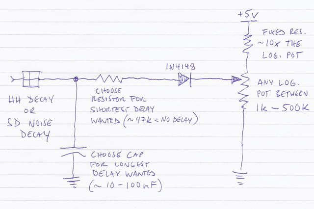
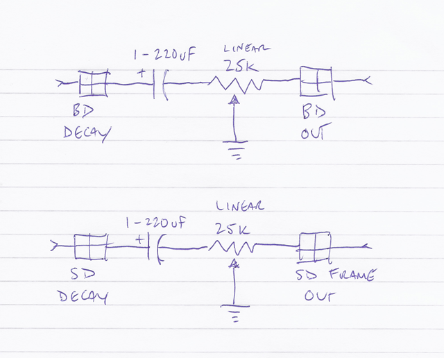
                    If you look at the schematics you can see that Korg has the BD DECAY and SD DECAY points at completely different places in their respective circuitry than the HH DECAY and SD NOISE DECAY points. Those two points (BD and SD) are rather misnamed - they really should be labelled SD GAIN and BD GAIN - because they're in the spot for gain adjustment of their respective unbypassed CE amplifiers. This means that when you connect a resistor or cap to ground from those points, you're not changing that sound's 'decay' by adding capacitance or resistance - you're actually shifting the gain and/or frequency response of the transistor amplifier for that sound. So the circuit used for these two points is different.

                    So here are some simple schematics to use the drum mod points with pots for a full range of settings:

                    The DECAY circuits (HH / SD NOISE):

                    Parts (for each circuit):
                    1x 1N4148 diode
                    1x log. potentiometer - any size between 1k - 500k, as long as you have a fixed resistor that is 10x larger.
                    1x resistor - 10x the size of the pot you use; e.g. if you use a 10k pot, you need a 100k resistor.
                    1x resistor - for the shortest decay you want. If you want zero decay (no volume) at one end of the pot, ~47k should work.
                    1x capacitor - for the longest decay you want. Perhaps 10 - 100nF, but you can experiment by just holding the cap from the labelled point to GROUND while listening to the rhythm at the slowest possible tempo. Make sure to listen via headphones (or line out) when testing.

                    Explanation:
                    The potentiometer sets the bias for the connected diode, thus determining the time at which the timing capacitors will discharge through it - from immediately (no sound) to never (maximum decay). The fixed resistor limits the maximum voltage at the pot wiper to the approx. drop of the diode.


                    The GAIN circuits (BD / SD FRAME):

                    Parts (for each circuit):
                    1x 25k linear potentiometer
                    1x capacitor - to set the bypassing (AC gain) of the respective amp. Perhaps 1uF - 220uF (I've been using 220uF for the BD, but I haven't experimented with SD FRAME yet), but you can experiment by just holding the cap from the labelled point to GROUND while listening to the rhythm. If you use a polarized cap, make sure the + side is to the labelled point. Make sure to listen via headphones (or line out) when testing.

                    Explanation:
                    The potentiometer forms a bypassed gain adjust for the respective amplifier. Turning the pot changes the amount of bypassing as well as the gain - from zero gain (no sound) to unbypassed gain (approximately the stock Korg sound - middle position) to completely-bypassed full gain (the sound with the added cap).

                    Comment


                    • #11
                      Wow, Outstanding!! And such informed and clear testimony too.. good job!

                      I actually have my Mono here in the shack for a look, as it's being picky about what MIDI it responds to. It ignores some of my older gear for some reason so, while im thinking about doing a more serious MIDI IN, some of this has to be applied.
                      The crudeness of switching in & out caps (etc.) means you have to have good timing to avoid clicks and pops, something more graduated and controllable is the way forward...
                      Last edited by -=GoD=-; Sun 13-07-2014, 6:07 PM.
                      jUst plAythAtbEAt

                      Comment


                      • #12
                        Originally posted by playthatbeat View Post
                        Wow, Outstanding!! And such informed and clear testimony too.. good job!

                        I actually have my Mono here in the shack for a look, as it's being picky about what MIDI it responds to. It ignores some of my older gear for some reason so, while im thinking about doing a more serious MIDI IN, some of this has to be applied.

                        The crudeness of switching in & out caps (etc.) means you have to have good timing to avoid clicks and pops, something more graduated and controllable is the way forward..
                        Thanks!

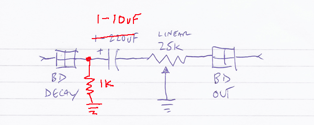
                        One other variation on the gain circuit from my last post that could be used to alter the tone of the BD (and SD) more, is to increase the gain of the amp before bypassing - as in the following schematic. If you do that, you need to decrease the bypass cap to avoid oscillation (in my test, I lowered it from 220u to 10u). This would make the max. pot sound closer to what you had when you added the 470R to ground.


                        The main drawback of this method is that the stock BD or SD sound is not returned when the amp becomes unbypassed (middle position of the pot), but if you don't care about that it could be a better solution.

                        BTW, I'm working on a solution to completely (hopefully) solve the click/pop problem on the MT. I think I'm on to something - and I'll post it here if it works.

                        Comment


                        • #13
                          I vaguely recall a range of pots that had a PUSH ON/PUSH OFF latching switch function.. They were a good space-saver combining pot & switch in one hole in the case, but also made for an interesting performance tool, where you could position the pot, then punch it in & out of the circuit. Maybe buffering one of these pots' switch with a small cap (as in how to reduce morse key clicks in CW ) would be a good plot for dealing with the shock of the mod(s) being turned on & off?
                          jUst plAythAtbEAt

                          Comment


                          • #14
                            A lot of great info here. Marmad your approach is really interesting I'll be playing around with this. I also came across a french forum with some good info on adding volume control to the individual SD,BD,HH. http://fr.audiofanzine.com/synthe-an...-kick,p.3.html

                            Comment


                            • #15
                              Seperate outs is something required i think.. i have never seen a machine that did not 'come to life' with a little bit of creative mixing.. if someone can adjust the levels of the parts, then You can tap these to outputs and go with some serious over-production lol
                              jUst plAythAtbEAt

                              Comment

                              Working...
                              X